Lidar based on linear array scanning has recently become an important method for distance measurement and 3D image acquisition. Many research groups have used an avalanche photodiode (GmAPD) as a detector in a 3D imaging lidar system due to its very high detection sensitivity and a simple readout integrated circuit. However, when using GmAPD in a 3D imaging radar system, there are some disadvantages. First, dark counts caused by thermal noise in the depletion zone will generate false alarms during the signal processing stage. Secondly, GmAPD has nothing to do with light intensity, indicating that it cannot distinguish between signal and noise. Therefore, in a radar system that uses GmAPD to obtain a clear 3D image, the noise elimination process is crucial.
MIT Lincoln Laboratory has developed a 3D imaging lidar system with GmAPD. Their 3D imaging radar system is a compact, lightweight system with excellent performance. However, it generates a lot of noise, so it takes a lot of time to remove the noise of a clear 3D image, because this is done through a series of image processing algorithms.
For clear 3D images, the phase of removing noise is essential. Therefore, we have developed a low-noise 3D imaging lidar system that can reduce false alarms by reducing the time of flight (TOF) data acquisition phase of the two original measurements, thereby obtaining clear 3D images at a fast acquisition speed . 1×8GmAPD array.
2 Low noise 3D imaging lidar system
The radar system is divided into two parts: its hardware and software. Figure 1 shows a schematic diagram of the radar system. Laser pulses are emitted from the light source and pass through the optical system. A small part of the laser pulse is used to generate the start signal, and the rest of the laser pulse irradiates the target. The receiving optical system collects part of the scattered laser pulses and background light in the field of view (FOV). Then, the laser return pulse and the background light are split in half by the beam splitter intensity and routed to the two GmAPD arrays. The "AND" gate compares the arrival time of the two GmAPD arrays, and only generates a stop signal when the time difference between the two signals from the GmAPD array is less than a fixed value. Although the signal is reduced by splitting the energy of the laser return pulse in half, 8]. The TOF data is the time difference between the start signal and the stop signal, which is generated on the TDC in the signal processing step. Then, in the image processing step, the TOF data is transmitted to a certain distance through the point cloud method to visualize the 3D image.
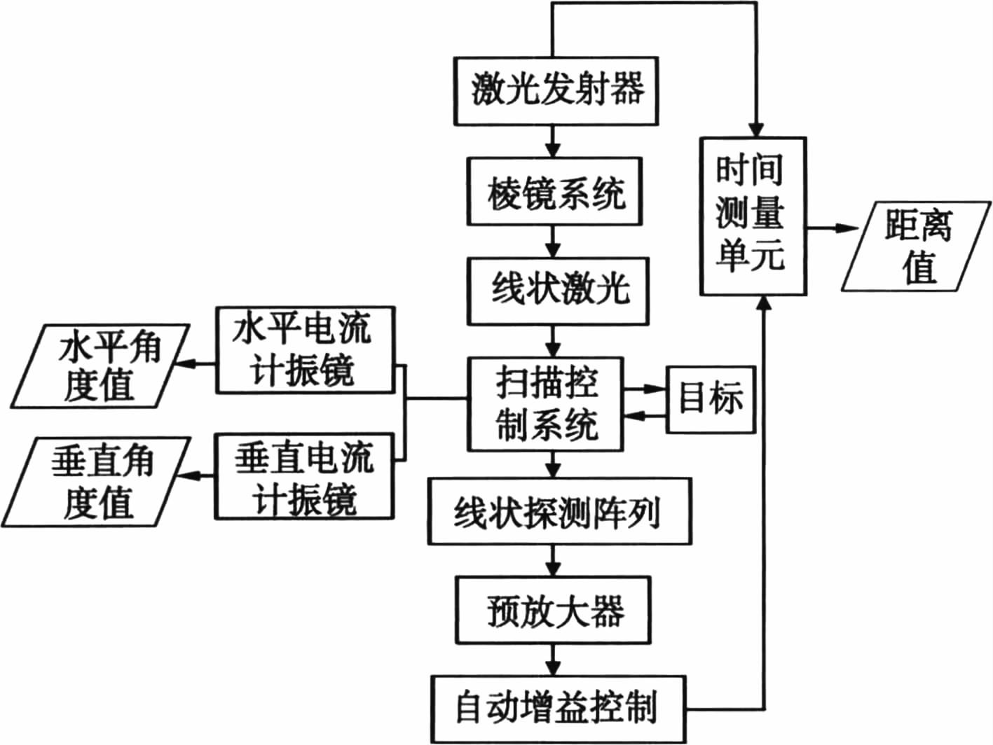
Figure 2 shows a two-dimensional image of the scene. The scene distance is about 60m. For GmAPD arrays 1 and 2, the average noise rate functions are 16kHz and 20kHz, respectively. This function is defined as the sum of the background photon rate impinging on the detector and the dark count rate of the GmAPD array. The three-dimensional image is scanned with 1164 points×1170 points, and the field of view (FOR) is 4°×4°. The figure shows the 3D images collected by one GmAPD array and two GmAPD arrays. The capacity of the 3D image file obtained by one GmAPD array is 162MB, and the capacity of the 3D image file obtained by two GmAPD arrays is 3.6MB.
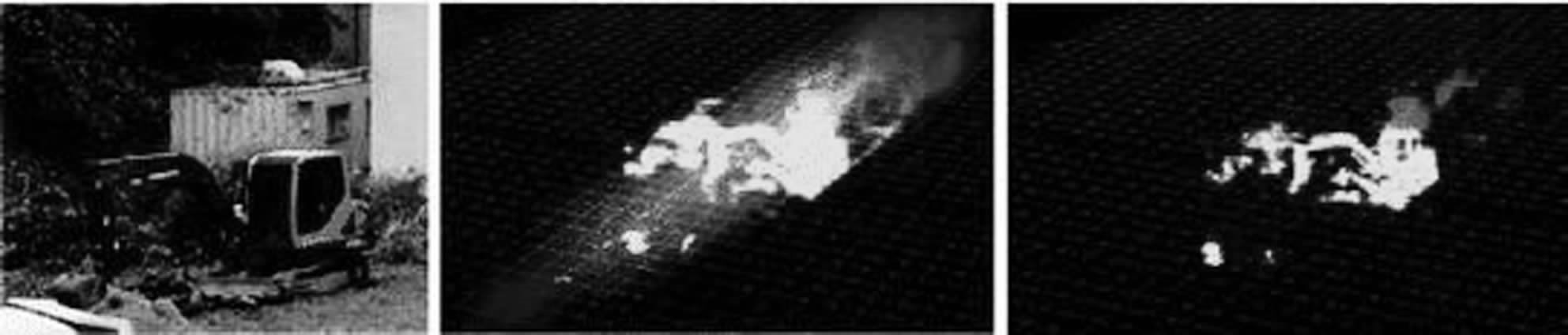
Figure 2
a. 2D image
b. 3D image obtained by a GmAPD array
c. The 3D image is acquired by two GmAPD arrays
2.1 Hardware
A diode-pumped passive Q-switched microchip laser with second harmonic generation (AlphalasPULSERAS-P-1064-300-FC/SHG) is used as the light source. Since the laser is passively Q adjusted, the start signal cannot be generated by the laser itself. Therefore, a small part of the laser pulse is transmitted to the photodiode at the 45° mirror. The PD used to generate the start signal is the Thorlab high-speed Si detector. The remaining laser pulses are reflected by the mirror and collimated by lenses L1 and L2. Due to the single polarization of the laser, the half-wave plate (HWP) is located before the polarization beam splitter (PBS) in order to control the transmission and reflection of the laser pulse at PBS1. The emitted laser pulse passes through the beam expander. The FOV of the system determined by the focal lengths of the lenses L3 and L4 and the beam expander is set to be the same as the divergence of the laser beam assuming Gaussian propagation. After the beam expander, the laser pulse is guided to the target by a two-axis current scanner, and then scattered. The two-axis current scanner used to control the beam pointing of the 1×8GmAPD array is from Cambridge Technology and has a 50mm aperture lens. The scattered laser pulses from the target and background light in the system FOV pass through a two-axis electrical scanner, a quarter wave plate (QWP), PBS1, and are collected by a two-axis electrical scanner into a GmAPD array (ID number id150-1×8 )in. The optical bandpass filter HWP2, PBS2 and focusing lens are arranged in this order. Because the microchip laser has a narrow spectral linewidth and temperature stability, the optical bandpass filter has six channels and a TDC (Agilent U1051A) with a timing resolution of 50 ps to receive the start and stop signals and measure the time difference between them. The function of the AND gate is to compare the TOF measured by GmAPD array 1 and GmAPD array 2. When the function of the AND gate is applied to TOF, due to the different time delay characteristics between each pixel in GmAPD, calibration is required. Arrays 1 and 2 are defined as a time period. The unit represents the time interval obtained by dividing the total measurement time by a specific value. By calculating the overall timing jitter of the system, the time period is set to 3ns.
A charge-coupled device (CCD) camera (Pix-elinkPL-B953U) with a fixed focal length lens is used as a boresight camera installed on the optical axis of the system to shoot the target. The FOV of the CCD camera is more in line with the FOV of the system.
2.2 Software
The algorithm executes a series of functional steps to convert the TOF data obtained by the system into a 3D image. After receiving the laser pulse, the system will provide a two-dimensional depth image, which includes angular depth data and 3D image visualization data for software processing. First, convert the TOF data to Cartesian positions. Use the scan angle and range information of each pixel to calculate the XYZ point in Cartesian coordinates. Using XYZ points, 3D image visualization can be performed through point cloud solutions. In the point cloud scheme, each XYZ point in the received data is simply drawn in 3D Cartesian coordinates.
3 range resolution and 3D image
The range resolution of a radar system is its ability to distinguish targets that are very close in range or bearing. In order to obtain the distance resolution of the system at 100 m, the standard deviation of the TOF of the proposed system was measured. The measurement target is positioned between 99.8m and 100.2m on the electric translation stage with an interval of 10cm. Use in every position
The standard deviation is obtained for 10,000 laser pulses. (Next to page 137) 3.2 Promote the implementation plan to be more scientific and carry out reasonable construction
Establish a sound and complete implementation plan to cultivate the competence of construction personnel, thereby improving the scientific nature of the implementation process. In the construction process, the staff carry out concrete construction according to the bridge design plan, and reasonably control the speed of concrete solidification according to the actual environment, thereby reducing the occurrence of cracks during the concrete solidification process. During the curing process, the construction personnel must carefully observe the changes of the concrete, and it is strictly forbidden to put pressure on the concrete before it is completely solidified. Secondly, maintaining moisture is also a point that cannot be ignored. Maintaining moisture can prevent cracks caused by excessive evaporation of moisture inside the concrete.
4 summary
This article introduces a low-noise 3D imaging radar system using two 1×8GmAPD arrays. Passively tuned Q-switched microchip lasers are used as light sources and cPCI systems, which include TDC and are set up for fast signal processing. The proposed radar system can obtain clear 3D images at a fast acquisition speed, which is achieved by using a 1×8GmAPD array in the TOF data acquisition phase to reduce false alarms. Developed software for 3D visualization for 1×8GmAPD array system. The distance resolution of the system was measured at 100m, and the 3D images collected by one GmAPD array and two GmAPD arrays during the day were displayed.
SureStar has been focusing on the development of LiDAR products and applications. All the "first" events related to LiDAR in China have been associated with SureStar.